WiFi Binary Clock
Who doesn't love a classic Binary Clock? I remember getting one of these when I was in my 20's from ThinkGeek, and it was pride of place on my desk. LED's are a thing of beauty.

Who doesn't love a classic Binary Clock? I remember getting one of these when I was in my 20's from ThinkGeek, and it was pride of place on my desk. LED's are a thing of beauty.
One thing that sucked about it though was it was a pain to set, it had no backup memory, and required an annoying AC power supply.
While moving at some stage, I've lost the clock, and they are still ridiculously expensive for what they are. So with that in mind, I decided to build a modern replacement for it.
There are several things a modern Binary Clock will need:
* WiFi - This allows for customisation, and allows for NTP Time Sync
* USB-C - Modern devices need modern power sources
* Simplicity - Keeping the parts list low is paramount to keeping the cost down
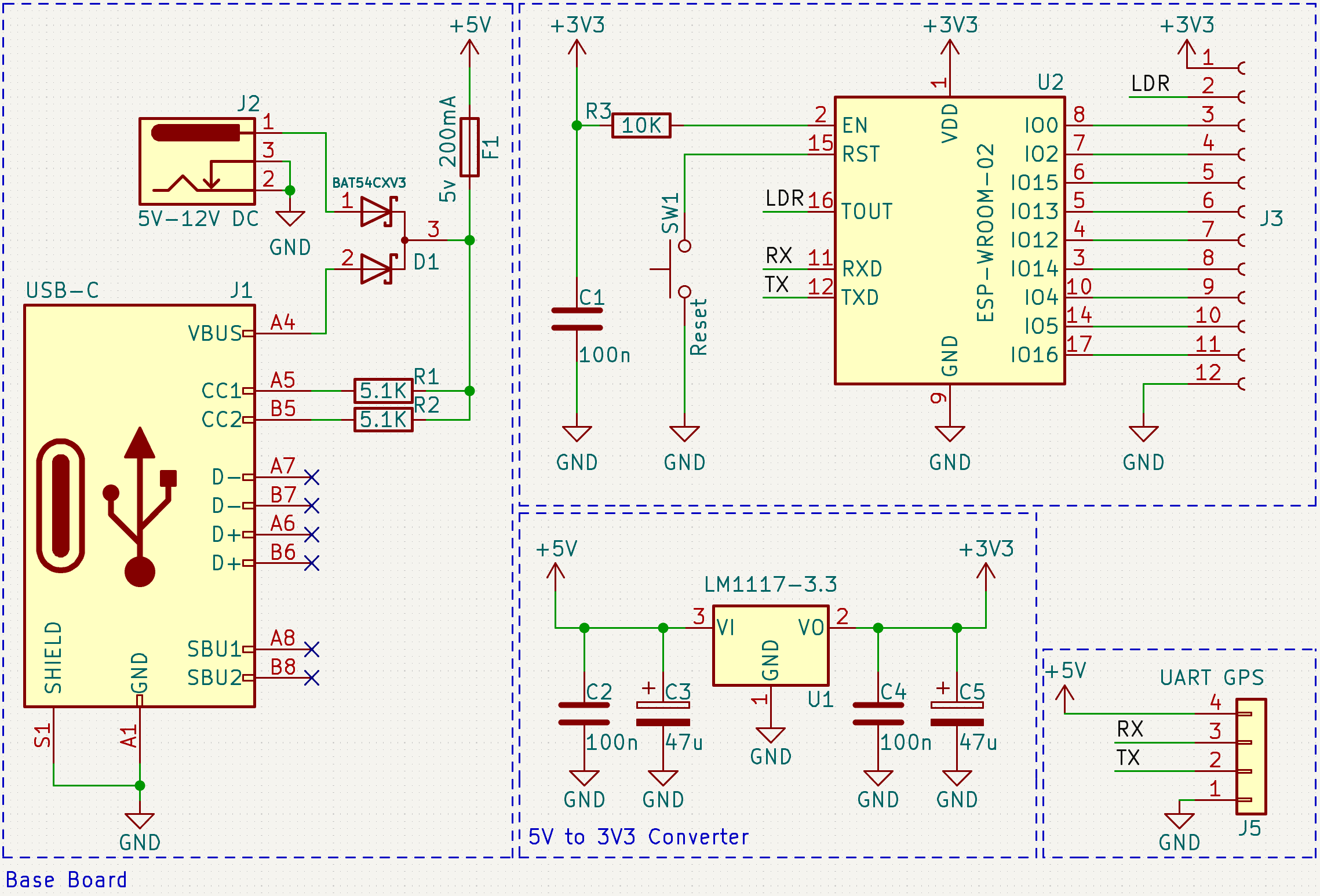
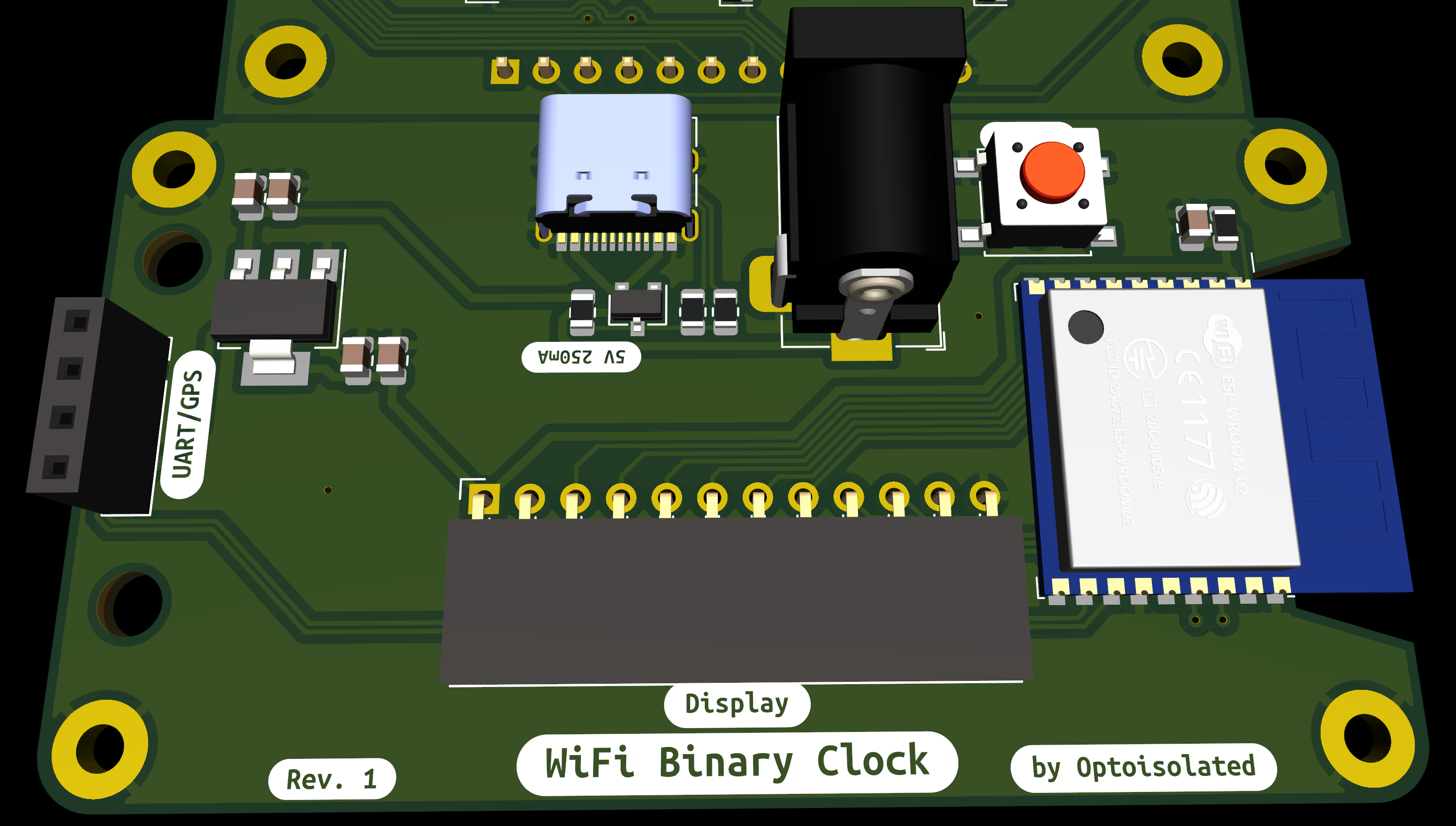
With this in mind, I opted for an ESP-WROOM-32 to drive the entire unit. I originally consider building at 74-series logic circuit to drive the BCD outputs, which would definitely work, and would give it legitimate classic electronics cred. The downside of this is it would limit its flexibility and increase the BOM cost. Having the entire unit controlled by the ESP simplifies the design greatly.
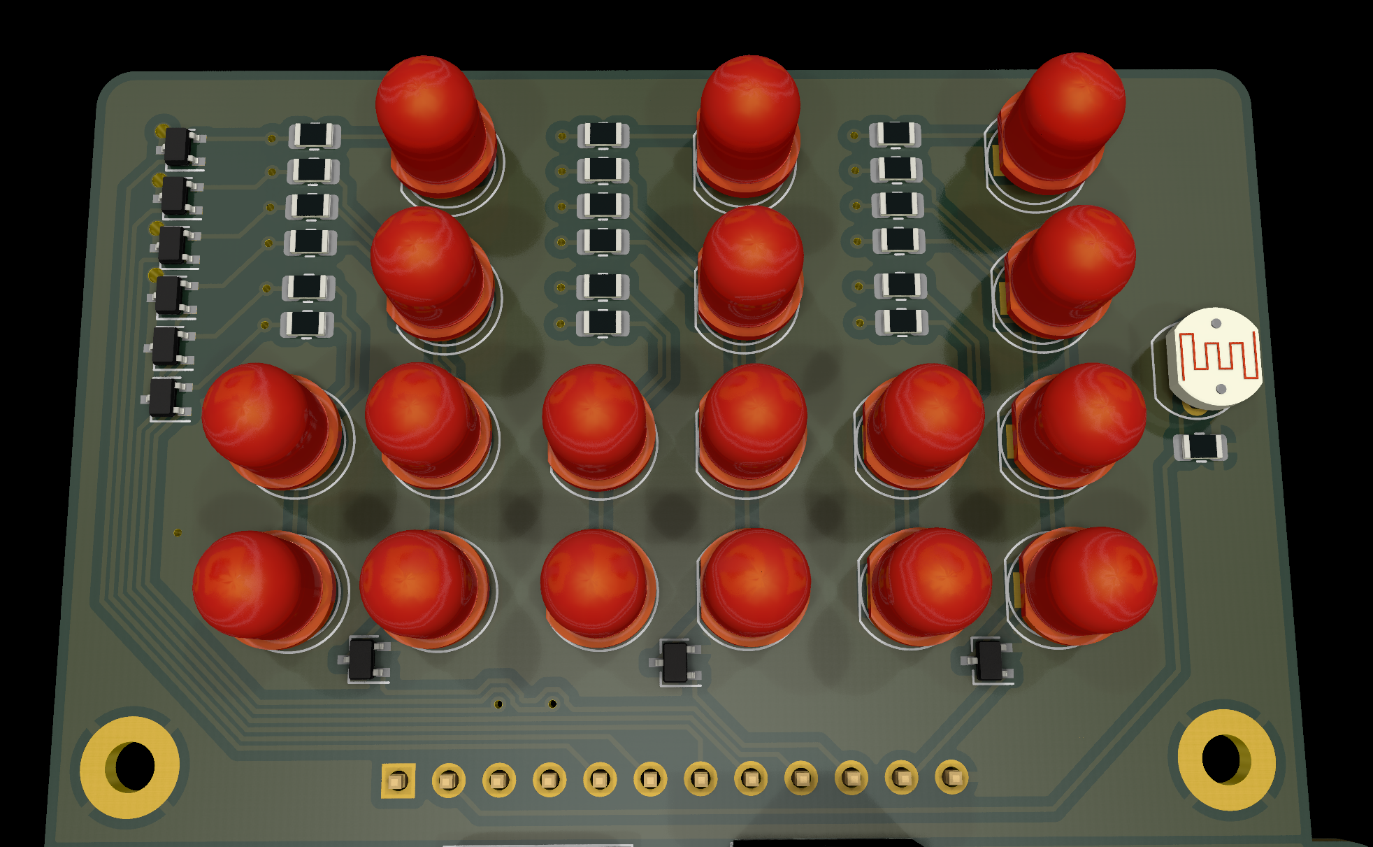
I originally wanted to use modern serial RGB SMD LEDs. This would allow the entire build to be surface-mount and keep the cost down, but the downside of that is it really takes away from the look and feel of a binary clock. I will likely make a second revision of this design which uses RGB SMD LEDs but for now, I opted for Through-hole 5MM LEDs.
Rather than a Matrix LED driver IC, which are hard to come by at present due to supply issues, I opted for slightly more complicated, but far cheaper transistor-driven matrix design. The matrix controlling can be handled by the ESP module.
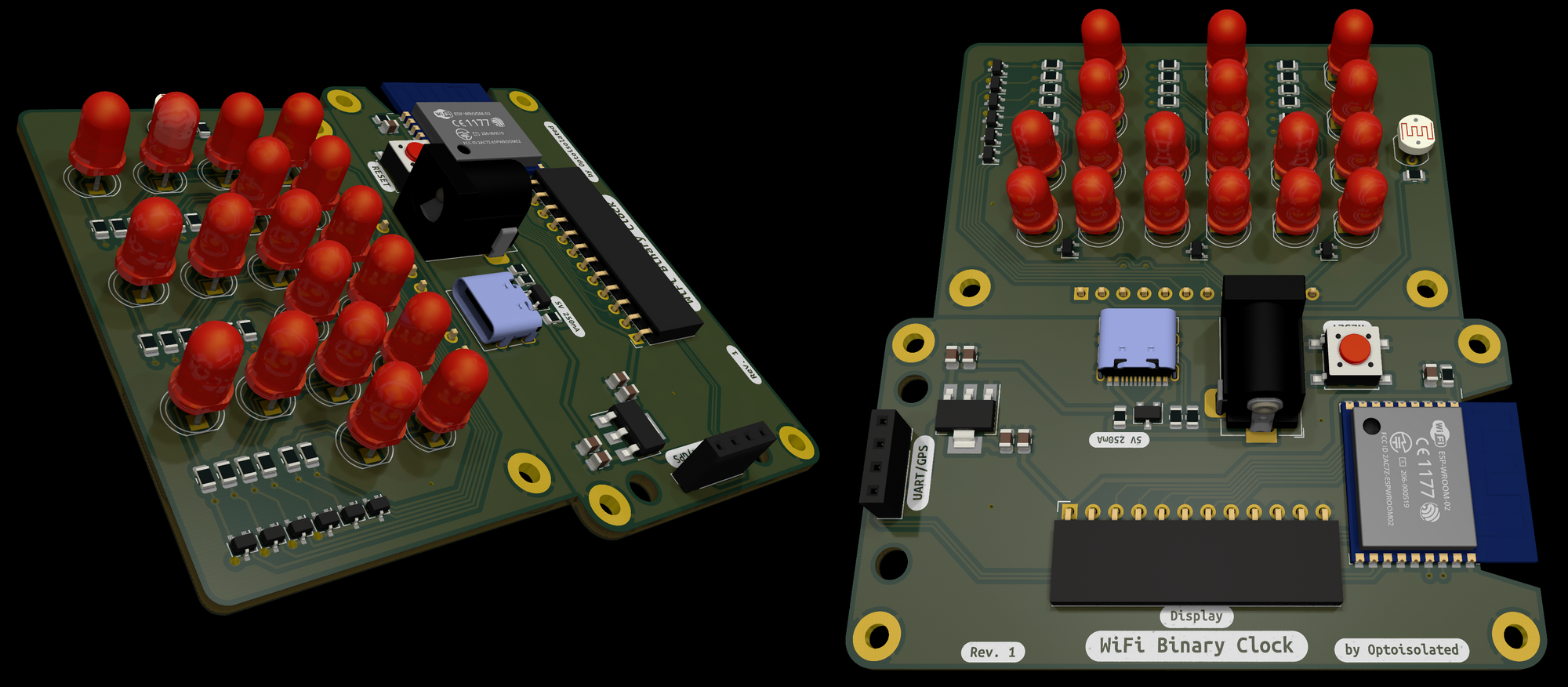
I've added dual power input options for both USB-C and classic DC-5V Barrel Jack connection. For an added bonus, and to make use of the unused TX/RX pins on the ESP module, I added the connector and layout for an optional Neo-6P GPS module. This will allow for the clock to be set automatically using GPS signal, without even needing WiFi. This won't be included by default, but is available if its desired.
One of the pet peeves of my original clock was it was blindingly bright in a dark room. To accommodate this, I've added an LDR on the display board (designed to be shrouded from the LEDs) to roughly measure the brightness of the room it is in, and adjust the LED brightness accordingly.
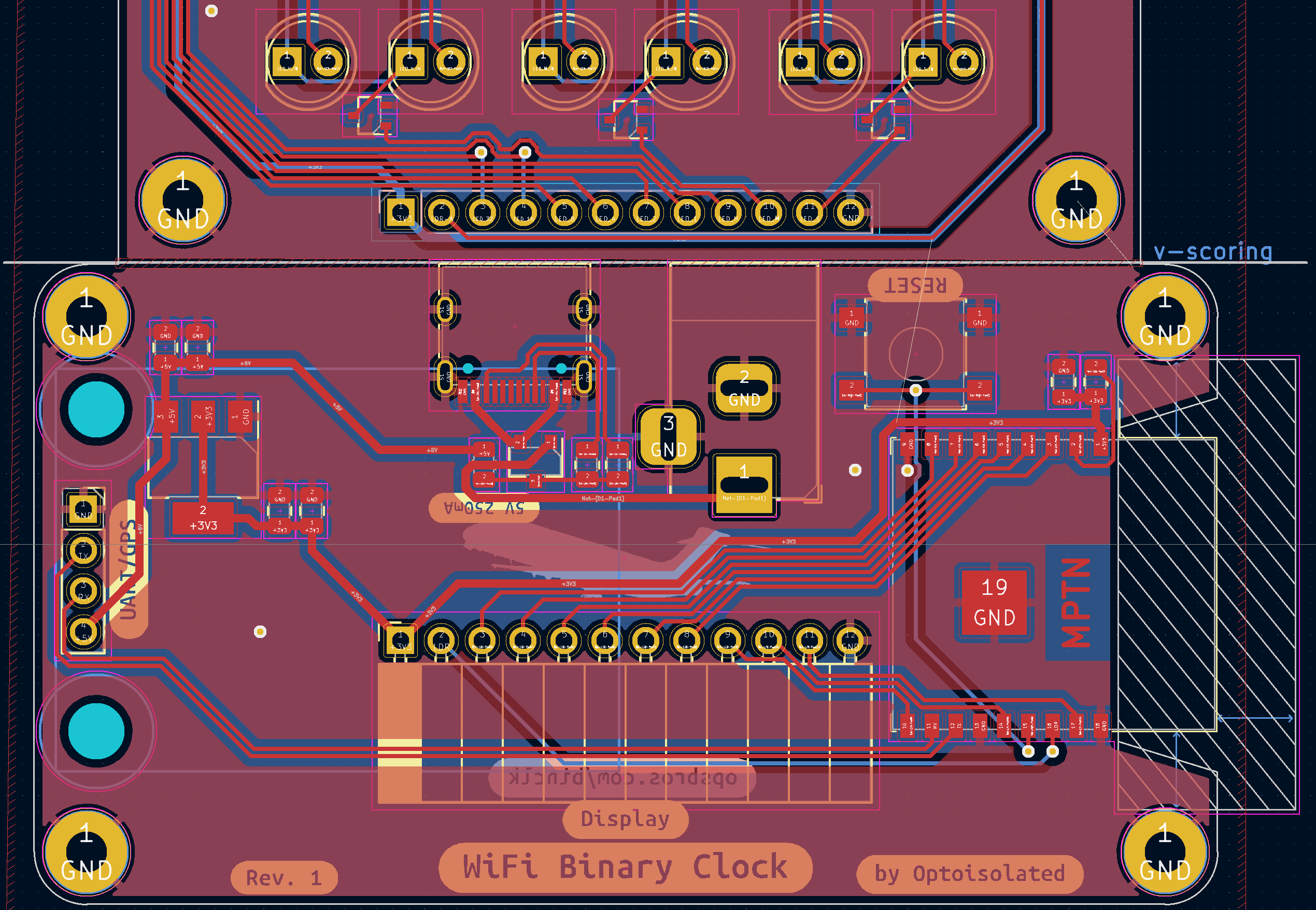
Finally, for the board layout I opted for a single PCB layout, which is designed to, one manufactured, to be snapped in half and the display board to be slid into the connector for the display on the main board. It's design to sit flush with the board with a few degrees off vertical attitude. This will give it a that classic on-desk viewing angle.
A case has not been designed yet, so it's designed to sit and operate without a case; however eventually I do want to design a 3D printable case for it.
Once the boards are back from JLCPCB, I will update this with some photos of the first designs and some code snippets. Stay tuned...