Volumer
I've always wanted a good USB volume control, so I decided to design one.

I've often been struggling with the rubbish volume control buttons on my keyboard at work, so I was traversing DuckDuckGo for a USB volume control and couldn't really find a good one. I did find a couple of arduino projects which would work, and looking into how they work, emulating the Media Keys, is both simple and effective way of controlling it. I really liked this approach. Continuing to browse, looking for one to buy, I came across this graphic.

It got me thinking... "I wonder if I could design a good USB volume control knob. Introducing the "Volumer".
When I made it home, I got right to work mapping out a design that would both be simple to make, yet look entirely stylish. As usual, I started with the design requirements:
- Must have a physical knob to control the volume of the PC
- Use a standard MicroUSB interface
- Work with standard USB drivers
- Small form factor (suitable for a 3D printed case)
- Must have SEXY SEXY Volume Level LEDs
- Push Button Mute
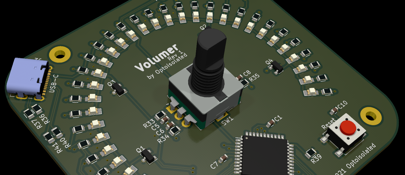
With that in mind, I started looking at part options. I defaulted to the EC11 rotary encoder as I know it's a solid encoder with plenty of travel, and supports push button as well (perfect to just 'tap-to-mute'). Next, the MCU. Again I opted for a classic in my repotoire with the ATMega32U4. Native USB support, ample IO pins, and relatively inexpensive considering its featureset. The rest of the componetry is bassicaly just passives (resistors, capacitors, diodes etc.)
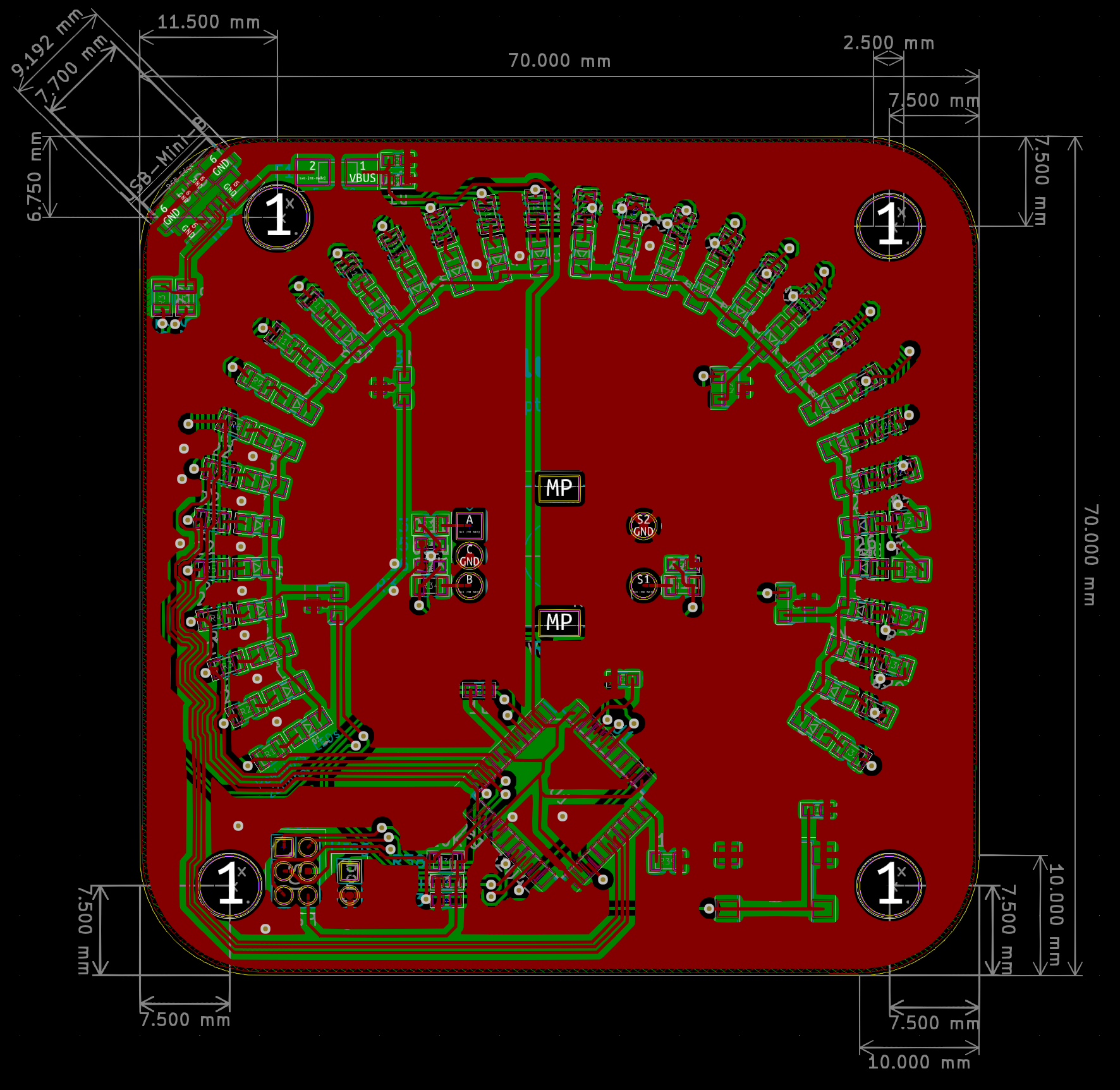
I took some advice I saw in a video made by Dave Jones of the EEVBlog where he said whenever you're working on a design, always assume that one day you may mass produce it. So I opted for an entirely surface-mount (SMD) design, for ease of assembly. Hand-soldering 32 LEDs and their associated resistors didn't sound fun. I also went for a fairly small form factor (70mm x 70mm), which would allow quite a few of these boards to be placed on one panel, and left room in the corners of the design to allow for panellised power supply and programming interfaces. This will allow me to test and program each of the mass-produced panels before they are broken out and assembled. The sizing also made it ideal for prototyping a 3D-printed case, and also ensuring it wouldn't take up too much valuable desktop real estate. The USB port is a corner mounted MicroUSB connector. Standard fare.
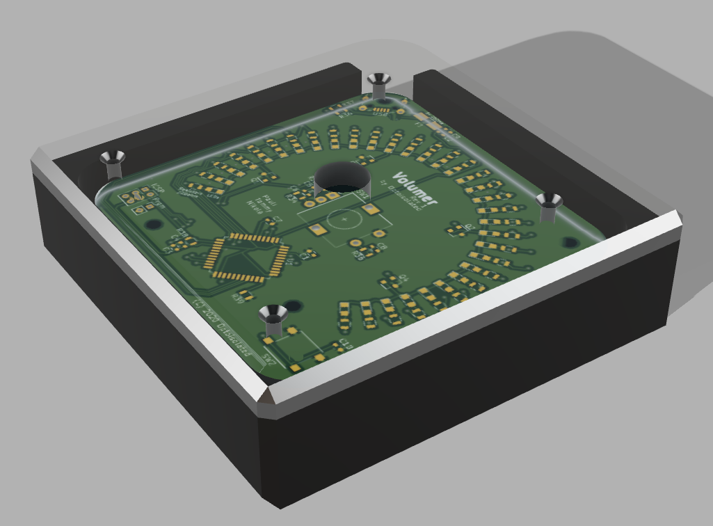
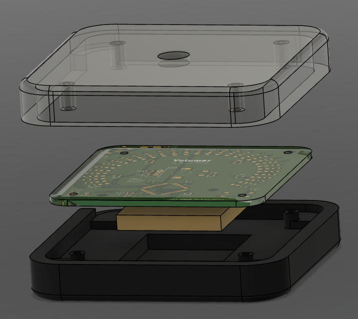
I shared this design with some colleagues in my works' maker community, and to my amazement, one of them was kind enough to whip up a 3D model for me, including some of the elements required to make it functional. We opted for a clear top and black bottom case, and space inside the case for a brass plate which would add mass to the unit. Important if you don't want it sliding around your desk too much.
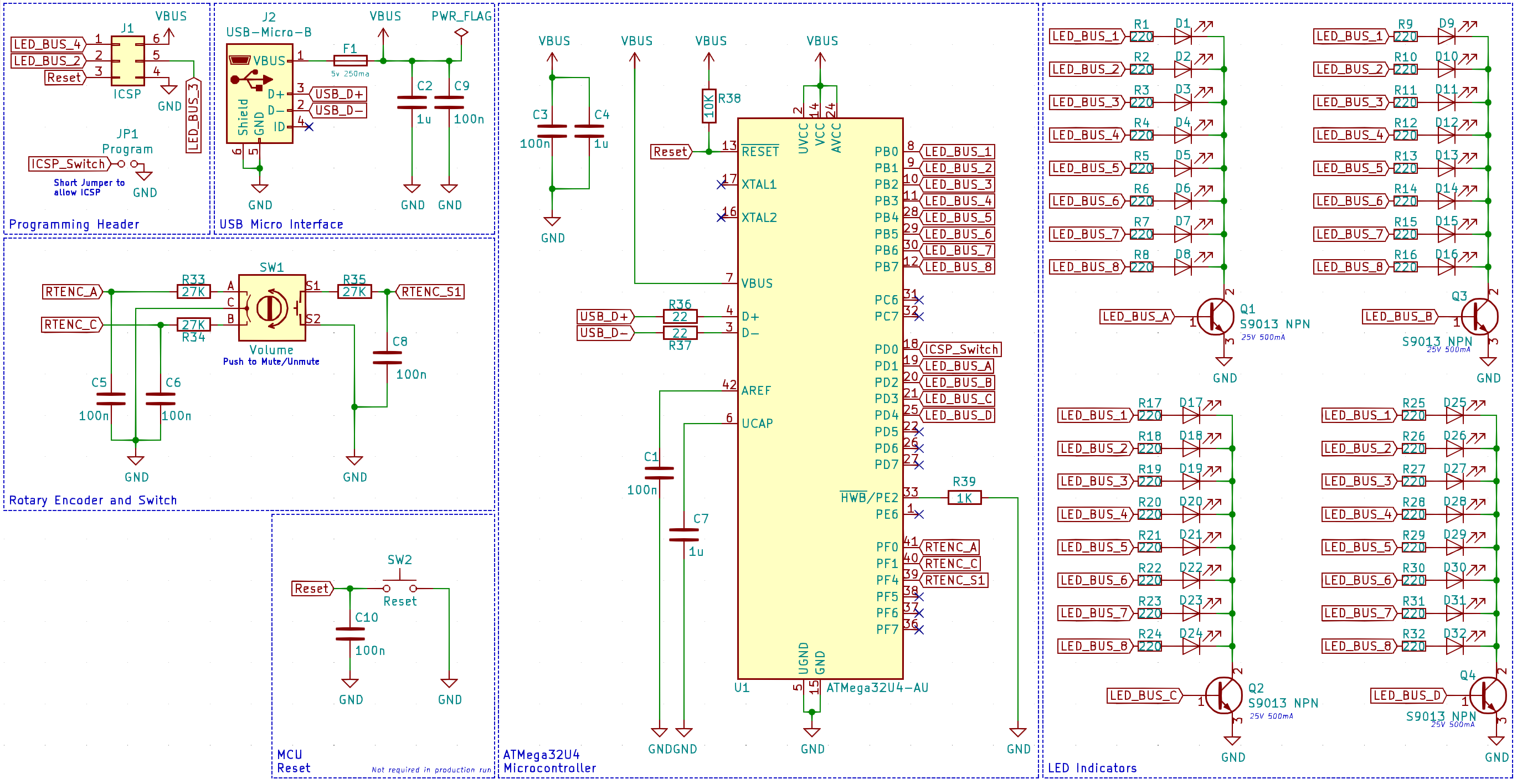
The schematic itself was relatively simple to design. The only novel part of the circuitry was that the 32 LEDs were broken up into groups of 8, and controlled by an NPN transistor in order to allow me to cycle through them at high speed. This reduce the number of IO pins needed from 32 to 12. Nice! No I/O expanders needed, that's a significant BoM saving.
Once that was finalised, I got to work on designing the PCB and quickly realised I was going to have to delve into an area of KiCad I had not played with previously. Python. After about 5 minutes of playing around with LED alignments, I realised I need to script the alignment and positioning of the LEDs. There was no way I was going to be able to cleanly and reliably position the LEDs and their corresponding current-limiting resistors on the board without using scripts.
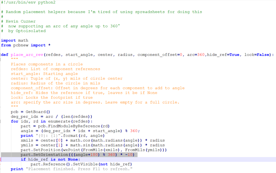
Enter the "placement_circle.py" script.
I found a script online that someone had developed that would allow you to place components rotated and stepped out from a circular centerpoint programatically designated in a python script. Perfect! Except, I need a semi-circle (or more accurately, a 3/4 circle). I started modifying the script and after about an hour of it failing, I realised I was struggling to figure out how this script was actually working. Foolishly, I tried to develop a new one based on my understanding of triginometry, and failing miserably (My Maths C lessons were flooding back to me, sorry Mr Phan, I'll get it next time.)
I then went back to the script and lo and behold after another hour of stuffing around with the parameterisation, I figured out how the original author was halding the rotation and positioning, and was able to successfully modify it to support not just circles, but an arc of any size. WINNING!
Where the issue was stemming from in my reviewing and modification of the script was that I didn't fully grasp how Kicad orientated parts by default, and then how the script was handling the orientation directly. It wasn't starting the arc where I thought it was. Because of that, whenever I modified the script I was messing up the start point, which resulted in a lot of messy positioning.
Anyway, after nutting that out; the script was updated (available on my Github), and the layout now had both LEDs and Current-limiting resistors correctly placed on the PCB.
I set to work positioning the rest of the componetry, remembering in the back of my mind that there would likely be a clear lid on this. Keeping the layout clean and orderly was very important.
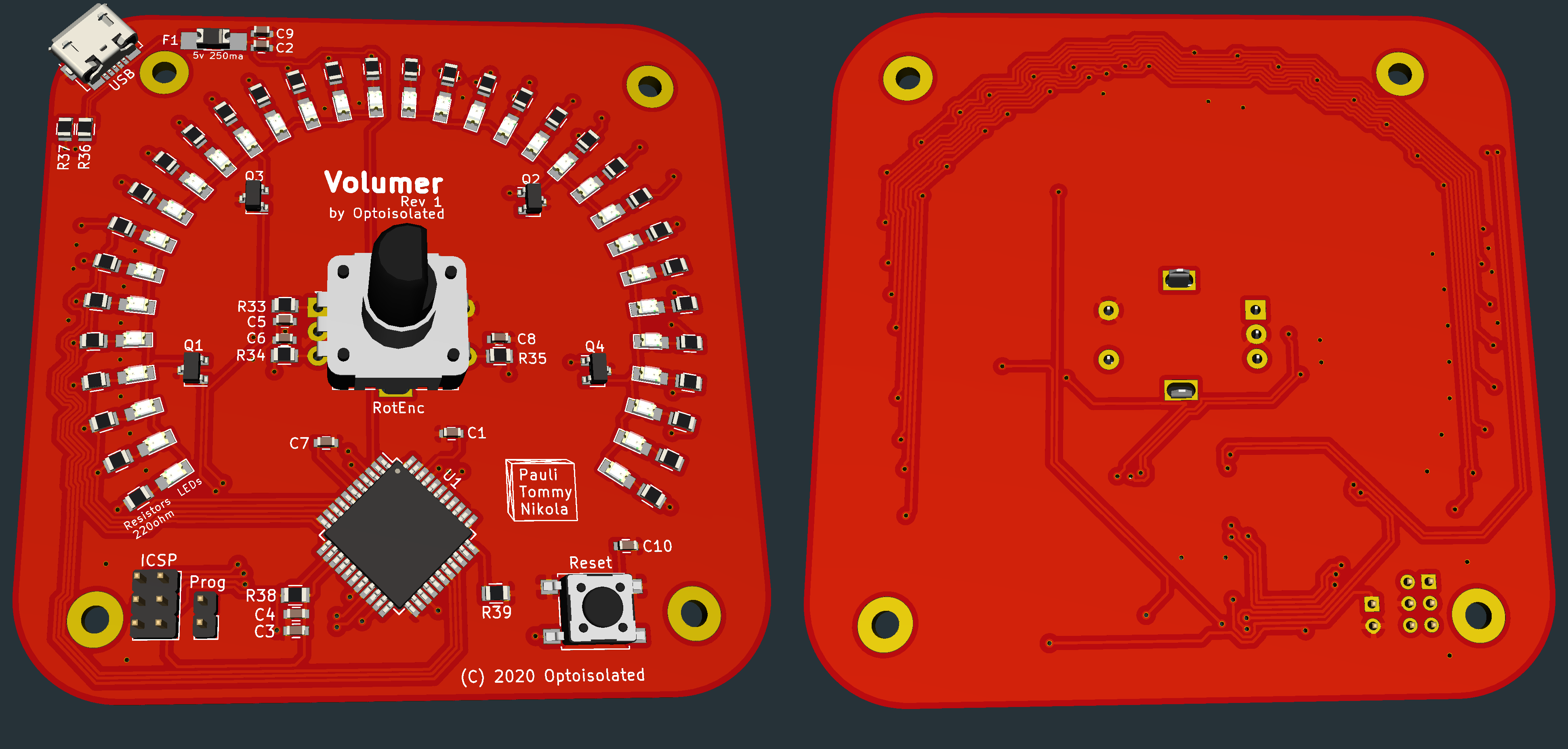
After many hours through trial and error working out the best way to route all of the 8 LED data lines to the IC, I finally settled on an approach you can see above that looks clean and minimised the number of vias I needed to put in the flow looking good. After that was completed, I felt pretty chuffed at the outcome. It looks very slick.
After I tidied up the Silkscreens and added some mounting holes (note the off-axis mounting hole at the top left due to the positioning of the USB port, which was unavoidable), I sent the PCB off to JLCPCB to be manufactured. Their turnaround time is usually only a week or so, but unfortunately due to China basically being shut down due to the Coronavirus, it took a lot longer. The board did eventually arrive however just yesterday, and I am pretty chuffed with how it turned out.
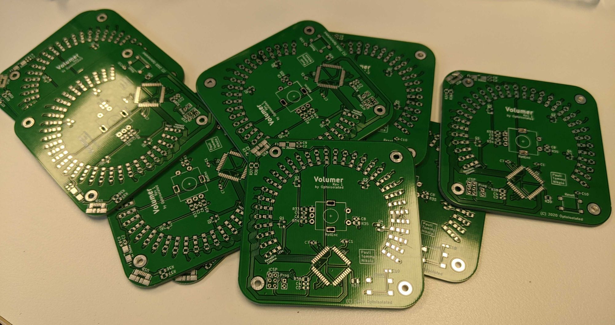
I opted for a green solder mask for the prototypes to both distinguish them from the final product, and also because the matt black solder mask is more expensive. I'll save that for the final product.
Once I'd finished this design, realised I really didn't want to hand-solder almost 100 components on these boards, so I set to work on my OpenReflow project to allow me to assemble these using a reflow oven.
That's where I'm up to. This one is going to be a great one to get going and I expect to have these for sale on my Tindie store, and on my web store by the end of July. Stay tuned.